Check the SIM800L module working condition:
Specification: SIM800L Hardware spec
GSM Standard: GSM Standard - ETSI TS 127 007 - AT Commands
Courtesy: https://nettigo.eu/products/sim800l-gsm-grps-module
Mini GSM/GPRS module
SIM800L is a miniature cellular module which allows for GPRS transmission, sending and receiving SMS and making and receiving voice calls. Low cost and small footprint and quad band frequency support make this module perfect solution for any project that require long range connectivity. After connecting power module boots up, searches for cellular network and login automatically. On board LED displays connection state (no network coverage - fast blinking, logged in - slow blinking).
NOTICE: Be prepared to handle huge power consumption with peek up to 2A. Maximum voltage on UART in this module is 2.8V. Higher voltage will kill the module.
Two antennas!
This module have two antennas included. First is made of wire (which solders directly to NET pin on PCB) - very useful in narrow places. Second - PCB antenna - with double sided tape and attached pigtail cable with IPX connector. This one have better performance and allows to put your module inside a metal case - as long the antenna is outside.
Specification
- Supply voltage: 3.8V - 4.2V
- Recommended supply voltage: 4V
- Power consumption:
- sleep mode < 2.0mA
- idle mode < 7.0mA
- GSM transmission (avg): 350 mA
- GSM transmission (peek): 2000mA
- Module size: 25 x 23cm
- Interface: UART (max. 2.8V) and AT commands
- SIM card socket: microSIM (bottom side)
- Supported frequencies: Quad Band (850 / 950 / 1800 /1900 MHz)
- Antenna connector: IPX
- Status signaling: LED
- Working temperature range: -40 do + 85 ° C
Set includes:
- SIM800L module
- goldpin headers
- wire antenna
- PCB antenna with pigtail and IPX connector
Module pinout
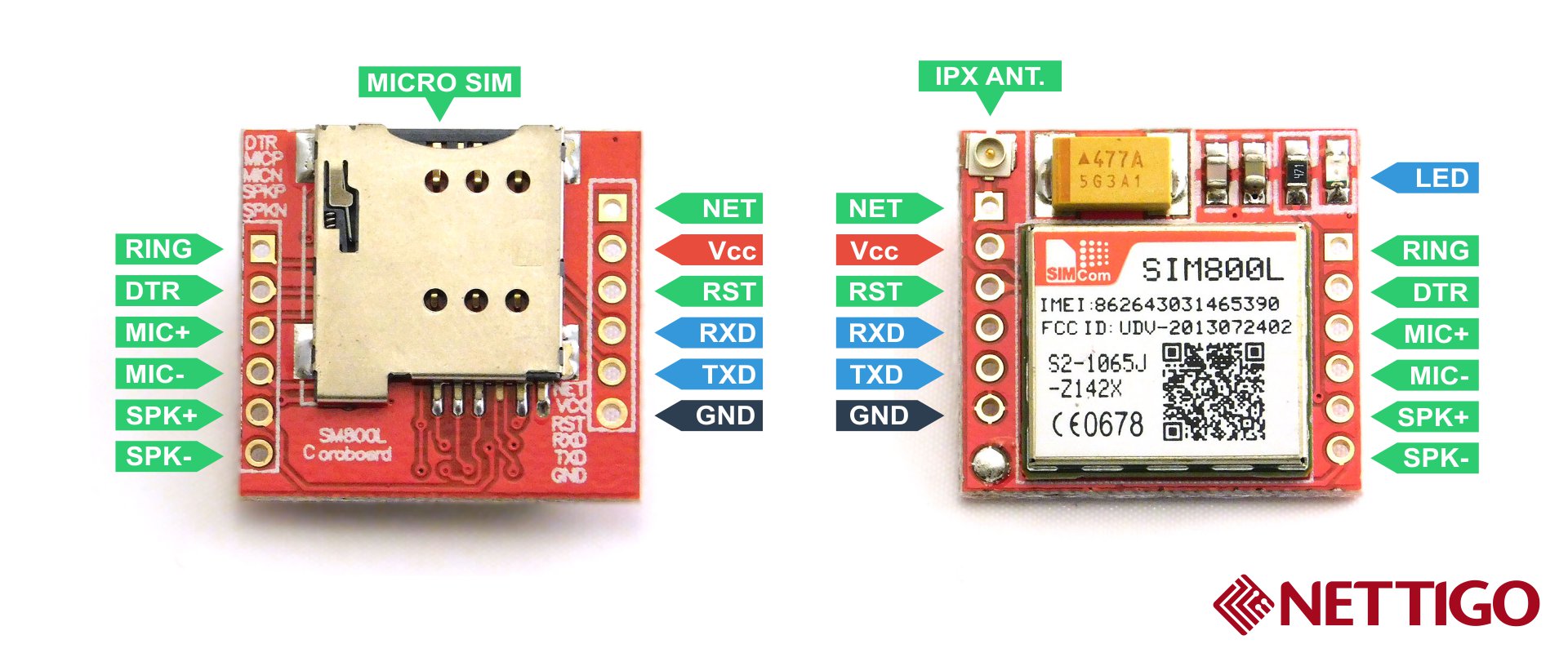
Pinout (bottom side - left):
- RING (not marked on PBC, first from top, square) - LOW state while receiving call
- DTR - sleep mode. Default in HIGH state (module in sleep mode, serial communication disabled). After setting it in LOW the module will wake up.
- MICP, MICN - microphone (P + / N -)
- SPKP, SPKN - speaker (P + / N -)
Pinout (bottom side - right):
- NET - antenna
- VCC - supply voltage
- RESET - reset
- RXD - serial communication
- TXD - serial communication
- GND - ground
Moreinfo : https://github.com/stephaneAG/SIM800L/blob/master/README.md
Sanity Test Connection:
1. Flash Arduino with empty code to connect SIM800L to laptop(Ardiuno act as USB to TTL converter)
void setup() {
// put your setup code here, to run once:
}
void loop() {
// put your main code here, to run repeatedly:
}
3. Connect Arduino 3.3 V to VCC supply 800L and remove the SIM card ()
3. Connect GND to Arduino GND
4. Connect RX to Arduino RX0
5. Connect TX to Arduino TX0
6. Open Serial Monitor and choose 9600 or any 115200 baud rate, CR and LF, since 800L is supports auto baud rate
init the auto-bauder: AT
OK
OK
get module name & version:ATI
SIM800 R14.18
SIM800 R14.18
turn on verbose errors:ATI+CMEE=2
SIM800 R14.18
SIM800 R14.18
get SIM card number:AT+CCID
get IMEI card number:AT+CGSN
get IMEI card number:AT+CGSN
to list available networks: AT+COPS=?
check that we're connected to a network:AT+COPS?
+COPS: 0
check that we're connected to a network:AT+COPS?
+COPS: 0
check signal strength:AT+CSQ
+CSQ: 26,0
+CSQ: 26,0
check battery state:AT+CBC =?
0 ME is not charging
1 ME is charging
2 Charging has finished
1...100 battery has 1-100 percent of capacity remaining
0000 - 4700
check battery state:AT+CBC (while i connected to 3.3v of Ardunio)
+CBC: 0,0,3286
pages: AT+CSCS=?
+CME ERROR: SIM not inserted
Observation: After inserting valid SIM CARD
check signal strength:AT+CSQ
+CSQ: 29,0
Syntax: Response +CSQ:,
0 -115 dBm or less,
1 -111 dBm,
2...30 -110...-54 dBm
31 -52 dBm or greater
99 not known or not detectable
(in %):
0...7 As RXQUAL values in the table in GSM 05.08 [20]
subclause 7.2.4
99 Not known or not detectable
check signal strength:AT+CSQ
+CSQ: 29,0
Syntax: Response +CSQ:
Powering Method #1:
Voltage divider :(led is not blinked at all and tx in Ardiuno keep flashing faster)
+5v ------(5 ohm ) R1 ------- (10* 2 ohm) R2-------->GND
|
+--------> VCC [SIM800L ] the voltage divider not working
GND -------------------------> GND [Module ]
Measured Current flow 180mA through resisters. Voltage across R2 is 4.1V and Heat dissipated in resisters. R1 (2*10 ohm connected parallel) and R2( 2* 10 ohm resister series).
I have tried replacing all 10 Ohm with 1K, but no use. Amps measure 1.2 mA only.
Summary: This method not worked
Why voltage divider doesn't work, since the resistor, since the resistors are 1/4 watt and its not good use high watt resistors , hence voltage regulator is suggested in that high amp power supply. Kindly refer hardware design doc of SIM800L.
Why voltage divider doesn't work, since the resistor, since the resistors are 1/4 watt and its not good use high watt resistors , hence voltage regulator is suggested in that high amp power supply. Kindly refer hardware design doc of SIM800L.
Powering Method #2:
5V through 20 ohm worked:
+5V -------R1----R2-------->VCC [SIM800L ]
GND ----------------------->GND [module ]
R1 - 10 ohm
R2 - 10 ohm
R1 - 10 ohm
R2 - 10 ohm
Note: Even 3*10 ohms not worked, TX of Ardiuno has n impact
+CBC: 0,100,5108
Syntax: Response +CBC:, ,
Syntax: Response +CBC:
bcs = 0 - Not charging, 1-charging, 2- finished
bcl = 1-100 % of battery level
Volt = mV
to list available networks: AT+COPS=?
Sample:
AT+COPS=?
+COPS: (2,"vodafone","voda UK","23415"),(3,"T-Mobile","TMO UK","23430"),(3,"O2","O2 -UK","23410"),,(0-4),(0-2)
OK
AT+COPS?
+COPS: 1
OK
+COPS: (2,"vodafone","voda UK","23415"),(3,"T-Mobile","TMO UK","23430"),(3,"O2","O2 -UK","23410"),,(0-4),(0-2)
OK
AT+COPS?
+COPS: 1
OK
summary:
If I try to get COPS=?(avil netwrk list), the Arduino Tx light keeps blinking ... seems voltage levels mismatch occurred b/w 800L and Ad's TX as occurred in voltage divider circuit, becoz searching network might draw more current.
You need more supply if u need to connect SIM and try ...( http://wiki.groundlab.cc/doku.php?id=microcontrollersgsm - not useful)
Tried by removing one 10 ohm resister from Powering Method #2:
list available networks: AT+COPS=?
+COPS: (1,"AIRCEL","AIRCEL","40442"),(1,"BPL USWEST (Tamil Nadu)","BPL MO","40443"),(1,"405044","405044","405044"),(2,"AirTel","AirTel","40494"),(1,"405852","405852","405852"),(1,"Tamil Nadu","CellOne","40480"),,(0-4),(0-2)
OK
check battery state:AT+CBC (while i connected to Vcc to 5.4V USB adapter(nubia 1A) and 10 Ohms and measured initially ~65mA, 14mA and 35mA and later LED blink per secs. And ~14mA. But if execute AT+COPS=? list network it raises till 85 mA max and later TX of Arduino blinks once for response.
+CBC: 0,100,5223
OK
AT+GSV
SIMCOM_Ltd
SIMCOM_SIM800L
Revision:1418B04SIM800L24
OK
AT+CSMINS? #is sim instered ? :
+CSMINS: 0,0
OK
AT+CSMINS=?
+CSMINS: (0,1)
OK
AT+CSMINS=1
OK
AT+CSMINS?
+CSMINS: 1,0
OK
AT+COPN
ERROR
AT+CMEE?
+CMEE: 0
OK
AT+CMEE=1
OK
AT+COPN
+CME ERROR: 10
at+cops
+CME ERROR: 100
AT+CMEE=2
OK
at+cops
+CME ERROR: unknown
at+cops?
+COPS: 0
OK
at+copn?
+CME ERROR: SIM not inserted
You can change the baud rate to 9600 on the SIM800L with the command:AT+IPR=9600
Then to save this (to last between boot cycles), give the commandAT&W
To see the saved settings, give the command:AT&V
Powering Method #3:
LM 317T: input source 12V 1Amps to LM317 but it seems board needs 2 Amps. LM can deliver 1Amps
Powered OFF the board and inserted the CARD, After inserting SIM Card , the output voltage dropped to less than 3.3v hence the board not functional and keeps restarting ..... :-(
RDY
+CFUN: 1
+CPIN: READY
AT+CBC
+CBC: 0,39,3714
OK
Call Ready
SMS Ready
AT+CBC
+CBC: 0,39,3719
OK
Call Ready
SMS Ready
AT+CBC
+CBC: 0,13,3511
OK
AT+CBC
+CBC: 0,0,0
Powering Method #4:
As suggested in SIM800L hardware design I choose
And its available in market as module ... U can buy Buck Converters .. Going to try ......
1 comment:
Hello.
I am running the SIM808 with Arduino Mega.
Using AT+ECHARGE=1 and AT&W to enable/store charging a LiPo for backup.
Doing AT+CBC always returns 0 for the first number, which means the LiPo is NOT charging.
Checking AT+ECHARGE? returns 1.
Shouldn´t AT+CBC return 1 in the beginning as well?
Thanks for any help.
Post a Comment