Saturday, January 11, 2020

Network performance tunning

Network performance tunning

Good Topic:
 Ref: https://blog.cloudflare.com/how-to-receive-a-million-packets/

HW Spec: They both have two 6-core 2GHz Xeon processors. With hyperthreading (HT) enabled that counts to 24 processors on each box. The boxes have a multi-queue 10G network card by Solarflare, with 11 receive queues configured. More on that later. 

Crash course to multi-queue NICs:
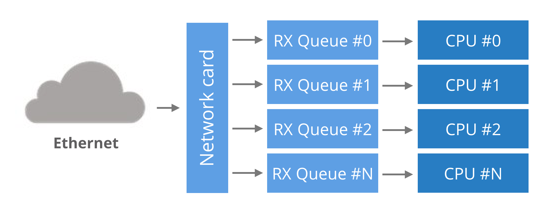
Historically, network cards had a single RX queue that was used to pass packets between hardware and kernel. This design had an obvious limitation - it was impossible to deliver more packets than a single CPU could handle.
To utilize multicore systems, NICs began to support multiple RX queues. The design is simple: each RX queue is pinned to a separate CPU, therefore, by delivering packets to all the RX queues a NIC can utilize all CPUs. But it raises a question: given a packet, how does the NIC decide to which RX queue to push it?
multiqueue nic
Round-robin balancing is not acceptable, as it might introduce reordering of packets within a single connection. An alternative is to use a hash from packet to decide the RX queue number. The hash is usually counted from a tuple (src IP, dst IP, src port, dst port). This guarantees that packets for a single flow will always end up on exactly the same RX queue, and reordering of packets within a single flow can't happen.
In our case, the hash could have been used like this:
RX_queue_number = hash('192.168.254.30', '192.168.254.1', 65400, 4321) % number_of_queues

Multi-queue hashing algorithms

The hash algorithm is configurable with ethtool. On our setup it is:
receiver$ ethtool -n eth2 rx-flow-hash udp4
UDP over IPV4 flows use these fields for computing Hash flow key:
IP SA
IP DA
This reads as: for IPv4 UDP packets, the NIC will hash (src IP, dst IP) addresses. i.e.:
RX_queue_number = hash('192.168.254.30', '192.168.254.1') % number_of_queues
This is pretty limited, as it ignores the port numbers. Many NICs allow customization of the hash. Again, using ethtool we can select the tuple (src IP, dst IP, src port, dst port) for hashing:
receiver$ ethtool -N eth2 rx-flow-hash udp4 sdfn
Cannot change RX network flow hashing options: Operation not supported
Unfortunately our NIC doesn't support it - we are constrained to (src IP, dst IP) hashing.
TIPS:(1) While we could have used the usual send syscall, it wouldn't be efficient. Context switches to the kernel have a cost and it is be better to avoid it. Fortunately a handy syscall was recently added to Linux: sendmmsg. It allows us to send many packets in one go.
TIPS:(2) Fortunately, there is a workaround recently added to Linux: the SO_REUSEPORT flag. When this flag is set on a socket descriptor, Linux will allow many processes to bind to the same port. In fact, any number of processes will be allowed to bind and the load will be spread across them.
With SO_REUSEPORT each of the processes will have a separate socket descriptor. Therefore each will own a dedicated UDP receive buffer. This avoids the contention issues previously encountered:
receiver$ taskset -c 1,2,3,4 ./udpreceiver1 0.0.0.0:4321 4 1
  1.114M pps  34.007MiB / 285.271Mb
  1.147M pps  34.990MiB / 293.518Mb
  1.126M pps  34.374MiB / 288.354Mb
This is more like it! The throughput is decent now!
More investigation will reveal further room for improvement. Even though we started four receiving threads, the load is not being spread evenly across them:
port uneven
Two threads received all the work and the other two got no packets at all. This is caused by a hashing collision, but this time it is at the SO_REUSEPORT layer.
-----------------------------------------------------------------------------------
== My Observation ==
Below shows how to check NIC is has how many RX-TX queues
[root@localhost ~]# cat /proc/interrupts | grep ens192
  57:   14481874    8881296     446331    2463896   PCI-MSI-edge      ens192-rxtx-0
  58:   11724321    5151965     722736    6279171   PCI-MSI-edge      ens192-rxtx-1
  59:       1339    4112623          0 1338260993   PCI-MSI-edge      ens192-rxtx-2
  60:  411242882  920999779          0    3695065   PCI-MSI-edge      ens192-rxtx-3
  61:          0          0          0          0   PCI-MSI-edge      ens192-event-4
[root@localhost ~]# 


(or) run below to show rx and tx queues
[root@localhost ~]# ls /sys/class/net/ens192/queues/
rx-0  rx-1  rx-2  rx-3  tx-0  tx-1  tx-2  tx-3
[root@localhost ~]# 
[ref]: You can see how many queues that you have available with: ethtool -S [interface]
If you have multiple queues enabled, they will show up. In addition you can watch traffic on the rx (tx) queues with the watch command:
watch -d -n 2 "ethool -S [interface] | grep rx | grep packets | column"
For Filtering Queues, use: tc qdisc show dev [interface]
If you have ADq or DCB queues they will show up here.
The documentation at https://www.kernel.org/doc/Documentation/networking/multiqueue.txt has a number of useful concepts and uses the tc command to manipulate the available multiqueue parameters. Without knowing your intentions, it's difficult to give a specific answer, but this information should get you pointed in the right direction.
-------------------------------------------------------------------------------------------------------------
TIPS:(3) RSS - Receive Side Scaling

In the previous article we mentioned that the NIC hashes packets in order to spread the load across many RX queues. This technique is called RSS - Receive Side Scaling. We can see it in action by observing the /proc/net/softnet_stat file with the softnet.sh script:
---------------------------------------------------------------------------------------------------------------


Tuesday, January 7, 2020

iptables Notes

How does iptables work?

other link: 
iptables is just a command-line interface to the packet filtering functionality in netfilter. However, to keep this article simple, we won’t make a distinction between iptables and netfilter in this article, and simply refer to the entire thing as “iptables”.
The packet filtering mechanism provided by iptables is organized into three different kinds of structures: tables, chains and targets. Simply put, a table is something that allows you to process packets in specific ways. The default table is the filter table, although there are other tables too.
Again, these tables have chains attached to them. These chains allow you to inspect traffic at various points, such as when they just arrive on the network interface or just before they’re handed over to a process. You can add rules to them match specific packets — such as TCP packets going to port 80 — and associate it with a target. A target decides the fate of a packet, such as allowing or rejecting it.
When a packet arrives (or leaves, depending on the chain), iptables matches it against rules in these chains one-by-one. When it finds a match, it jumps onto the target and performs the action associated with it. If it doesn’t find a match with any of the rules, it simply does what the default policy of the chain tells it to. The default policy is also a target. By default, all chains have a default policy of allowing packets.

Tables

As we’ve mentioned previously, tables allow you to do very specific things with packets. On a modern Linux distributions, there are four tables:
  • The filter table: This is the default and perhaps the most widely used table. It is used to make decisions about whether a packet should be allowed to reach its destination.
  • The mangle table: This table allows you to alter packet headers in various ways, such as changing TTL values.
  • The nat table: This table allows you to route packets to different hosts on NAT (Network Address Translation) networks by changing the source and destination addresses of packets. It is often used to allow access to services that can’t be accessed directly, because they’re on a NAT network.
  • The raw table: iptables is a stateful firewall, which means that packets are inspected with respect to their “state”. (For example, a packet could be part of a new connection, or it could be part of an existing connection.) The raw table allows you to work with packets before the kernel starts tracking its state. In addition, you can also exempt certain packets from the state-tracking machinery.
In addition, some kernels also have a security table. It is used by SELinux to implement policies based on SELinux security contexts.

Chains

Now, each of these tables are composed of a few default chains. These chains allow you to filter packets at various points. The list of chains iptables provides are:
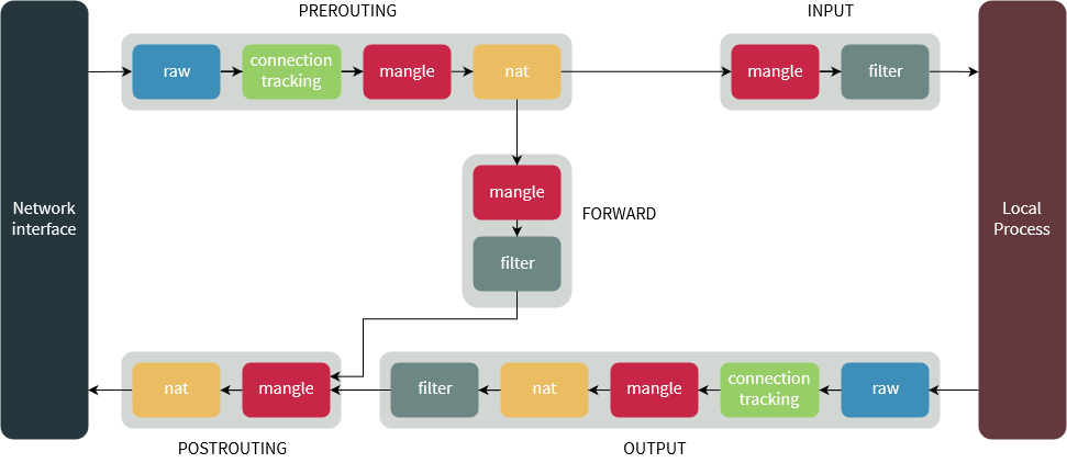
  • The PREROUTING chain: Rules in this chain apply to packets as they just arrive on the network interface. This chain is present in the nat, mangle and raw tables.
  • The INPUT chain: Rules in this chain apply to packets just before they’re given to a local process. This chain is present in the mangle and filter tables.
  • The OUTPUT chain: The rules here apply to packets just after they’ve been produced by a process. This chain is present in the raw, mangle, nat and filter tables.
  • The FORWARD chain: The rules here apply to any packets that are routed through the current host. This chain is only present in the mangle and filter tables.
  • The POSTROUTING chain: The rules in this chain apply to packets as they just leave the network interface. This chain is present in the nat and mangle tables.
The diagram below shows the flow of packets through the chains in various tables:


Targets

As we’ve mentioned before, chains allow you to filter traffic by adding rules to them. So for example, you could add a rule on the filter table’s INPUT chain to match traffic on port 22. But what would you do after matching them? That’s what targets are for — they decide the fate of a packet.
Some targets are terminating, which means that they decide the matched packet’s fate immediately. The packet won’t be matched against any other rules. The most commonly used terminating targets are:
  • ACCEPT: This causes iptables to accept the packet.
  • DROP: iptables drops the packet. To anyone trying to connect to your system, it would appear like the system didn’t even exist.
  • REJECT: iptables “rejects” the packet. It sends a “connection reset” packet in case of TCP, or a “destination host unreachable” packet in case of UDP or ICMP.
On the other hand, there are non-terminating targets, which keep matching other rules even if a match was found. An example of this is the built-in LOG target. When a matching packet is received, it logs about it in the kernel logs. However, iptables keeps matching it with rest of the rules too.
Sometimes, you may have a complex set of rules to execute once you’ve matched a packet. To simplify things, you can create a custom chain. Then, you can jump to this chain from one of the custom chains.

Blocking IPs

The most common use for a firewall is to block IPs. Say for example, you’ve noticed the IP 59.45.175.62 continuously trying to attack your server, and you’d like to block it. We need to simply block all incoming packets from this IP. So, we need to add this rule to the INPUT chain of the filter table. You can do so with:
iptables -t filter -A INPUT -s 59.45.175.62 -j REJECT
Let us break that down. The -t switch specifies the table in which our rule would go into — in our case, it’s the filter table. The -A switch tells iptables to “append” it to the list of existing rules in the INPUT chain. However, if this is the first time you’re working with iptables, there won’t be any other rules, and this will be the first one.
As you might have guessed, the -s switch simply sets the source IP that should be blocked. Finally, the -j switch tells iptables to “reject” traffic by using the REJECT target. If you want iptables to not respond at all, you can use the DROP target instead.
Previously, we’ve mentioned that the filter table is used by default. So you can leave it out, which saves you some typing:
iptables -A INPUT -s 59.45.175.62 -j REJECT
You can also block IP ranges by using the CIDR notation. If you want to block all IPs ranging from 59.145.175.0 to 59.145.175.255, you can do so with:
iptables -A INPUT -s 59.45.175.0/24 -j REJECT
If you want to block output traffic to an IP, you should use the OUTPUT chain and the -d flag to specify the destination IP:
iptables -A OUTPUT -d 31.13.78.35 -j DROP
Listing rules:
iptables -L --line-numbers
Deleting Rules:
iptables -D INPUT -s 221.194.47.0/24 -j REJECT
Flush all the INPUT rules
iptables -F INPUT

Friday, July 5, 2019

Java Decimal Round of Understanding:

double[] doubleList= {
        0.001,
        0.0012,
        0.00123,
        0.001234,
        0.0012345,
        0.1234567,
        0.0000001,
        0.0000005,
        0.0000006,
        0.0000009,
     1234.00000001,
        0.00000005,
        0.00000006,
        0.00000009,
        0.111111111,
        0.000000005,
        0.000000006,
        0.000000009,
        1.9,
        0.09,
        0.009,
        0.00999,
        0.009999,
        0.0099999,
        0.00999999,
        0.999999999};
for (double d:doubleList) {
    System.out.println("   round7: "+roundOfForBilling(d)+" val="+d );
}
public static double  roundOfForBilling(double value) {
    DecimalFormat df = new DecimalFormat("0.0000000");
    df.setRoundingMode(RoundingMode.UP);
    //df.setMaximumFractionDigits(7);    
    System.out.print(" format:"+df.format(value)+
                     " rm="+df.getMaximumFractionDigits());
    return Double.parseDouble(df.format(value));
}
Output:
 format:0.0010000 mode=UP   round7: 0.001     val=0.001
 format:0.0012000 mode=UP   round7: 0.0012    val=0.0012
 format:0.0012300 mode=UP   round7: 0.00123   val=0.00123
 format:0.0012340 mode=UP   round7: 0.001234  val=0.001234
 format:0.0012345 mode=UP   round7: 0.0012345 val=0.0012345
 format:0.1234567 mode=UP   round7: 0.1234567 val=0.1234567
 format:0.0000001 mode=UP   round7: 1.0E-7    val=1.0E-7
 format:0.0000005 mode=UP   round7: 5.0E-7    val=5.0E-7
 format:0.0000006 mode=UP   round7: 6.0E-7    val=6.0E-7
 format:0.0000009 mode=UP   round7: 9.0E-7    val=9.0E-7
 format:1234.0000001 mode=UP   round7: 1234.0000001 val=1234.00000001
 format:0.0000001 mode=UP   round7: 1.0E-7    val=5.0E-8
 format:0.0000001 mode=UP   round7: 1.0E-7    val=6.0E-8
 format:0.0000001 mode=UP   round7: 1.0E-7    val=9.0E-8
 format:0.1111112 mode=UP   round7: 0.1111112 val=0.111111111
 format:0.0000000 mode=UP   round7: 0.0       val=5.0E-9
 format:0.0000000 mode=UP   round7: 0.0       val=6.0E-9
 format:0.0000000 mode=UP   round7: 0.0       val=9.0E-9
 format:1.9000000 mode=UP   round7: 1.9       val=1.9
 format:0.0900000 mode=UP   round7: 0.09      val=0.09
 format:0.0090000 mode=UP   round7: 0.009     val=0.009
 format:0.0099900 mode=UP   round7: 0.00999   val=0.00999
 format:0.0099990 mode=UP   round7: 0.009999  val=0.009999
 format:0.0099999 mode=UP   round7: 0.0099999 val=0.0099999
 format:0.0100000 mode=UP   round7: 0.01      val=0.00999999
 format:1.0000000 mode=UP   round7: 1.0       val=0.999999999

RoundingMode.UP
RoundingMode.DOWN        we use this more 0.00000 you will find
RoundingMode.HALF_UP     (but this reduce)
RoundingMode.HALF_EVEN

Monday, June 3, 2019

MYSQL Useful commands:


1. TO Get the Database size in Mysql

SELECT table_schema AS 'Database Name', ROUND(SUM(data_length + index_length) / 1024 / 1024, 2) AS 'Size in (MB)' FROM information_schema.TABLES GROUP BY table_schema;

2. Take Schema backup ( backup with no data )
mysqldump -u root -p --no-data dbname > schema.sql

Saturday, June 16, 2018

Java Understanding


Java Design pattern....

1) Singleton Pattern. 
2) Factory - The instance of varies similar object will be available in single point. Hence maintenance  is easy. simply same kind of object can be removed
3) Model View Controller   -  Link : http://en.wikipedia.org/wiki/File:MVC-Process.svg 
4) Model View Presenter - 
5) FODA - Feature Oriented Design - To build the Mandatory , Optional and Dependent feature for the image
6) Facada - Act as Abstract for a module
7) Observable Patter

ASOP - Aspect oriented Programming in Spring.
OSGI - Concept to upgrading a class object without stopping the server ... in on the line

- Static Proxy - apache has
- Dynamic Proxy
- Generics -

JCP - Java Community Programming  - Forum to decalre interfaces eg servlet, JAIN sip, etc ... 

Tuesday, January 2, 2018

Aloe Vera Cultivation


http://www.expert-market.com/aloe-vera-farming-a-profitable-business-to-start-business-plan/

Different varieties of Aloe vera which is very popular in trade are:- Chinensis , Littorallis and Aloe Abyssinica are the different varieties of aloe vera however for aloe vera farming in india IEC 111271 , AAL1 , IEC 111269 are highly productive hybrid for farming.
Selection of land in Aloevera farming:- Initially 2 acre of land is needed for the profitable outcome at the beginning of Aloe Vera farming.it  is generally cultivated in the dry region with minimal rainfall and warm humid region.  So the suitable selection of land is required with dry region and low water stagnantation soils. Sandy soils are the best for its cultivation also well drained black cotton soils is very suitable for the perfect growth of Aloe Vera farming. In land selection we should select those land which is at little height with ground level so as to avoid rain water stagnation also the well drained light sandy soil is best.
Land Ploughing in Aloe Vera farming:- before starting of monsoon the field should be well prepared. Its time to plough the land. Land should be thoroughly ploughed till the soil become fine separated and drained. In order to increase the fertility of land just add 10 to 15 tonnes of organic farm yard maure. The PH of the soil should be 8.5 with the adequate salt content.
Propagation and Planting of aloe Vera :- Aloe Vera plant is propagated by rhizome cutting and also from root suckers, for its propagation the underground rhizome is dug out and suitable length recommended  5-5.5 cms is cut which must contain minimum of two to three nodes in it first it should be rooted in sand beds or particular container after its sprouting it is ready for the plantation. Similarly the root suckers is dug out from the parent plant and should be planted with a separation of 50×45 cms and length of rhizome cutting and root suckers must be in 12-15cms range. It is highly advisable that the two third portion of the plant should be inside ground.
Irrigation and pest control:-
After proper plantation the irrigation must be done as per the moisture content of the soil. Pest control is also very necessary step to be taken in order to avoid damage to the plant. Mealy Bug is the major threat to the aloe vera crop and the major disease is the spotting of leaves.
So for the aloe vera weeding plan proper spraying of 0.1% of parathion or 0.2% of malathion aqueous solution is needed. Also 0.2% dithane M-45 spraying should be done weekly to prevent from leaf spot.
Aloe vera harvesting:- If everything is done as prescribed above there would be a very profitable harvesting time. In almost 8 months first harvesting can be done. Manual harvesting is needed as the broken rhizome left in the soil will sprout again so special attention must be taken while harvesting the aloe vera plant. From the second year there would be a commercial yield of aloevera crop and will last upto 5 years. So from the second year the profit margin will grow unexpectedly. An average of 8,000 to 10,000 kg of aloe vera crop is obtained from 2 Acre of land.
http://www.agrifarming.in/cost-and-profits-of-aloe-vera-farming/


Tuesday, October 31, 2017

SIM800L Module Bringup


Check the SIM800L module working condition:
Specification: SIM800L Hardware spec
GSM Standard: GSM Standard - ETSI TS 127 007 - AT Commands
Courtesy: https://nettigo.eu/products/sim800l-gsm-grps-module

Mini GSM/GPRS module

SIM800L is a miniature cellular module which allows for GPRS transmission, sending and receiving SMS and making and receiving voice calls. Low cost and small footprint and quad band frequency support make this module perfect solution for any project that require long range connectivity. After connecting power module boots up, searches for cellular network and login automatically. On board LED displays connection state (no network coverage - fast blinking, logged in - slow blinking).
NOTICE: Be prepared to handle huge power consumption with peek up to 2A. Maximum voltage on UART in this module is 2.8V. Higher voltage will kill the module.

Two antennas!

This module have two antennas included. First is made of wire (which solders directly to NET pin on PCB) - very useful in narrow places. Second - PCB antenna - with double sided tape and attached pigtail cable with IPX connector. This one have better performance and allows to put your module inside a metal case - as long the antenna is outside.

Specification

  • Supply voltage: 3.8V - 4.2V
  • Recommended supply voltage: 4V
  • Power consumption:
    • sleep mode < 2.0mA
    • idle mode < 7.0mA
    • GSM transmission (avg): 350 mA
    • GSM transmission (peek): 2000mA
  • Module size: 25 x 23cm
  • Interface: UART (max. 2.8V) and AT commands
  • SIM card socket: microSIM (bottom side)
  • Supported frequencies: Quad Band (850 / 950 / 1800 /1900 MHz)
  • Antenna connector: IPX
  • Status signaling: LED
  • Working temperature range: -40 do + 85 ° C

Set includes:

  • SIM800L module
  • goldpin headers
  • wire antenna
  • PCB antenna with pigtail and IPX connector

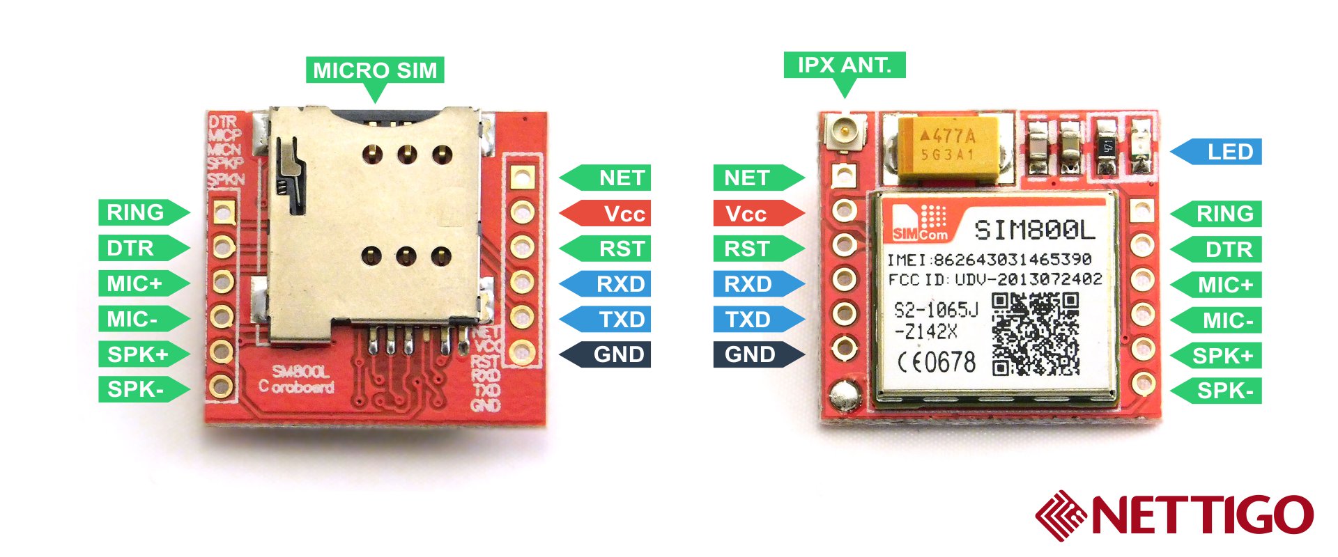
Module pinout

ModuĊ‚ GSM GPRS SIM800L Pinout


Pinout (bottom side - left):
  • RING (not marked on PBC, first from top, square) - LOW state while receiving call
  • DTR - sleep mode. Default in HIGH state (module in sleep mode, serial communication disabled). After setting it in LOW the module will wake up.
  • MICP, MICN - microphone (P + / N -)
  • SPKP, SPKN - speaker (P + / N -)
Pinout (bottom side - right):
  • NET - antenna
  • VCC - supply voltage
  • RESET - reset
  • RXD - serial communication
  • TXD - serial communication
  • GND - ground
Moreinfo : https://github.com/stephaneAG/SIM800L/blob/master/README.md 

Sanity Test Connection: 


1.  Flash Arduino with empty code to connect SIM800L to laptop(Ardiuno act as USB to TTL converter) 

void setup() {

  // put your setup code here, to run once:

}

void loop() {

  // put your main code here, to run repeatedly:

}

3. Connect Arduino 3.3 V to VCC supply 800L and remove the SIM card ()
3. Connect GND to Arduino GND
4. Connect RX to Arduino RX0
5. Connect TX to Arduino TX0
6. Open Serial Monitor and choose 9600 or any 115200 baud rate, CR and LF, since 800L is supports auto baud rate


init the auto-bauder: AT
OK
get module name & version:ATI
SIM800 R14.18
turn on verbose errors:ATI+CMEE=2
SIM800 R14.18
get SIM card number:AT+CCID

get IMEI card number:AT+CGSN
to list available networks: AT+COPS=?

check that we're connected to a network:AT+COPS?
+COPS: 0
check signal strength:AT+CSQ
+CSQ: 26,0
check battery state:AT+CBC =?
+CBC: (0-2),(1-100),(voltage)
: Charge status
    0 ME is not charging
    1 ME is charging
    2 Charging has finished
: Battery connection level
    1...100 battery has 1-100 percent of capacity remaining

: Battery voltage(mV)
     0000 - 4700
check battery state:AT+CBC   (while i connected to 3.3v of Ardunio)
+CBC: 0,0,3286

pages: AT+CSCS=?
+CME ERROR: SIM not inserted

Observation: After inserting valid SIM CARD
check signal strength:AT+CSQ

+CSQ: 29,0
Syntax:  Response +CSQ: ,
  0 -115 dBm or less,
                 1 -111 dBm, 
                 2...30  -110...-54 dBm
                 31 -52 dBm or greater 
                 99 not known or not detectable 
(in %): 0...7 As RXQUAL values in the table in GSM 05.08 [20] subclause 7.2.4 
                 99 Not known or not detectable